|
WSE
Series DC/AC Manual Wolfram Argon Arc Welding Machine
|
| This
series adopts W-CE electrode with argon as protective medium. It is AD and DC universal argon arc welding machines.
It has four functions of use: AC TIG welding, DC TIG welding, AC
manual arc welding and DC manual arc welding. It can weld
high, mid or low carbon steel, non-ferrous metals and its
alloy. It has such properties as wide applying range, easy
operation, stable and reliable performance. |
 |
First.
The main purpose and the scope of application
WSE
AC and DC welding machine by using tungsten electrode in argon
atmosphere for the protection of media, use AC or DC arc welding machine
for welding. Welder can be welded carbon steel, stainless steel, alloy
steel, copper, aluminum and other more active resistance to high
temperature and chemical properties of metallic materials. acidic or
alkaline can be used for manual welding electrode. 380V,50Hz welder
using single-phase AC power.
Second.
The main technical parameters and specifications
Specifications
and the main technical parameters shown in Table 1.
Main technical parameters and specifications
in Table
1
|
Project
|
Units
|
Models
and parameters
|
|
WSE-200
|
WSE-315
|
WSE-400
|
WSE-500
|
|
Rated
input voltage
|
V
|
380
|
380
|
380
|
380
|
|
Rated
input current
|
A
|
38
|
65
|
83
|
110.5
|
|
No-load
output voltage
|
V
|
78
|
78
|
80
|
80
|
|
Welding
current scope of regulation
|
A
|
AC:30-200
|
AC:40-320
|
AC:40-400
|
AC:1
stall 33A-200A
2
stall 152A-580A
|
|
DC:20-180
|
DC:30-300
|
DC:38-300
|
DC:1
stall 33A-185A
2
stall 135A-500A
|
|
Admission
arc current scope
|
A
|
No
|
30-50
|
30-50
|
30-50
|
|
Admission
arc time
|
S
|
No
|
10
|
10
|
10
|
|
Gas
delay time
|
S
|
10
|
20
|
20
|
20
|
|
Duty
cycle
|
%
|
60
|
60
|
60
|
60
|
|
Torch
cooling
|
|
Without
water
|
water-cooled
|
|
Dimension
(L×W×H)
|
mm
|
700×460×750
|
810×490×820
|
900×480×800
|
890×570×900
|
Third.
The principle and structure outlined
Welder
used moving core transformer, the full-wave bridge and rectifier filter
inductance is output
characteristics, so that the filter inductor DC welding output, the
current stability in exchange output, the current zero speed.
By
welding transformer, control transformer, single-phase rectifier bridge,
filter inductance, capacitance at DSS. High-frequency oscillator,
transformers, circuit boards and control solenoid valve, the gun and
various switches.
The
aircraft is equipped with a current figure panel installation
instructions, explicit instructions welding current values. Welder shell
shape is beautiful, strong, durable facilitate disassembly, lifting and
transfer characteristics.
The
stability and resumption arc is that the crater fill function that can
significantly improve the quality of welding.
Fourth.
The use and operation
4.1
Welder only allowed to
use at
ambient temperature 5-40°C,
relative humidity of less than 90%. not to allow harmful gases,
flammable and near the desert, steam spray, mold and other occasions.
also prohibited conductivity dust.
4.2Welder
must have good grounding, earthing wire cross-sectional area larger than
the cross-sectional area of importation.
4.3
Welding
power supply from the power grid, power and welding equipment should
control switch. fuse should be consistent with the machine, welding
output line will have to be good insulation and attention to the plane
in line with the supply voltage.
4.4
When the welder used to extend
the distance
from the welding site welding cables, welding cables must be increased
cross-sectional area. welding cable voltage drop is less than four voltage,
burning arc stability can affect the quality of welding.
4.5
Welding operators to be trained professionally familiar with the
technical requirements for the safe operation of aircraft and equipment,
Safety must wear protective equipment, visual arc not prevent
electroslag spatter, so as to avoid adverse consequences.
4.6
Finishing work or leaving the workplace, must be cut off the power.
4.7
Installed and connected
Installation
and connect Chart
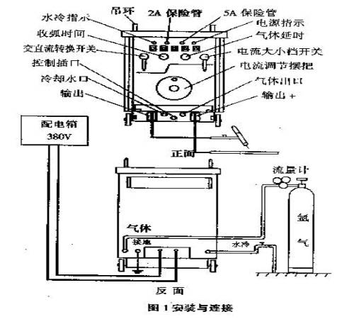
Welding315 : 1. water out 2.gas out 3.
Line of Control Interface
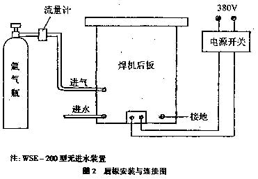
Welding200:
1、2
welder Line of Control Interface 3. Vent Interface
Note
: 1、any
changes to the design, printing faced by welding symbols prevail.
2、when
the welding for manual arc welding, and not Needling gas, water.
4.8
Operating procedures
4.8.1
Using Tungsten Inert Gas (TIG)
A. According to the brochure 4.7,
gas
road and
the lines
are connected all the good.
B.
Face knob and switch to a suitable location, AC-DC switch must grant
place.
C.
According to the current requirements, the use of
regulatory shake
regard to the appropriate location adjustment instructions.
D.
Power Switch appropriated to the "open" position when the
power lights, rotating fans.
Fans
will not be diverted, repair and inspection of stands, not to use.
E.
Frederick Frederick gas income into position switch to gas, argon gas
flow adjustment flowmeter instructions, Switch will be adjusted income
into working position.
F.
Work.
4.8.2
Use SMAW
A.
The
statement by wiring, welding guns will be removed, to take over the
welding tongs.
B.
Switch on the panel will be transferred to the required location.
C.
Regulation shake regard, the spin current direction of the required
position.
D.
Switching power supply will be allocated, the bright light, rotating
fans, a no-load output voltage.
Fans
will not be diverted, not to use.
E.
Started welding.
Fifth.
repair and maintenance
5.1
Welding machine during maintenance or repair, we should cut off the
power supply.
5.2
Welder
regular internal cleansing, casing removed, and air dry cleaning
internal components, parts.
5.3
Factory welder has been transferred to the best electrical sparks up,
the use of such high frequency sparks decline easy arc starting, it
would be appropriate to adjust the electrical sparks up the gap,
reaching arc in the best condition. inspection of the main circuit and
high-frequency oscillation circuit connection and prevent Pretend
welding, Sealing-off phenomenon.
5.4
Welding cable insulation must regularly check whether good, if damage to
be repaired or replaced.
Sixth.
The general troubleshooting
General
troubleshooting table below. Before the repairs, cut off the power the
repair work by competent personnel.
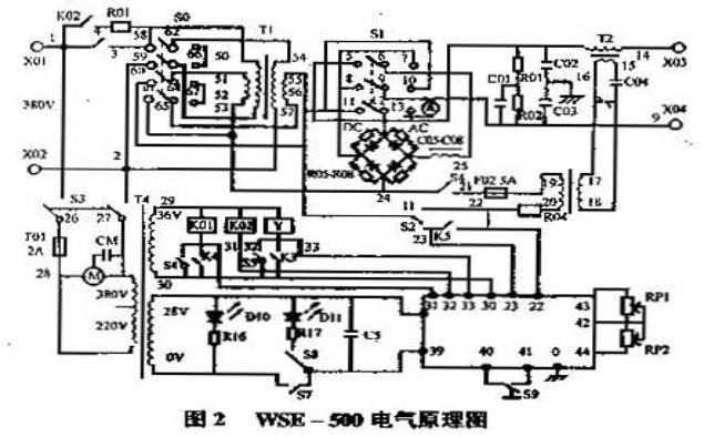
Inspection
failure, electrical diagram reference welder
|
Fault
|
Reasons
|
Approach
|
|
Power
short circuit
|
1.
Switch damage.
2.
Fans short circuit or damage.
3.
Control transformer short-circuit or damage.
4.
Short-circuit or damage to the Line of Control.
5.
Contactors, relays, solenoid valve short circuit.
|
1.
Replacement
2.
Replacement
3.
Replacement
4.
Repair
5.
Replacement
|
|
No
action procedures
|
1.
Control insurance damage.
2.
Damage Control Board.
3.
Control Circuit broken.
4.
Pressure switch damage.
5.
Waterway nowhere.
|
1.
Replacement
2.
Replacement
3.
Overhaul
4.
Replacement
5.
Overhaul
|
|
HF
no sparks
|
1.
Damage HF insurance.
2.
High-frequency circuit nowhere.
3.
Too much dust.
4.
Control Board Damage.
5.
High-frequency transformer damage.
6.
High-frequency capacitance damage.
|
1.
Replacement
2.
Replacement
3.
Clean
4.
Replacement
5.
Replacement
6.
Replacement
|
|
Normally
aspirated
|
1.
Valve damage.
2.
Control Circuit nowhere.
3.
Damage Control Board.
|
1.
Replacement
2.
Overhaul
3.
Replacement
|

|